|
This chapter explores programming a CICS application in COBOL.
It uses the Payroll application as an example and describes the coding required for both the presentation logic and business logic portions of the application.
4.1 Presentation logic
The only way to truly understand the concepts described in earlier sections is to have a look at the code that makes up the Payroll application.
If you recall, there are two programs PAYPGM and PAYBUS that make up the presentation and business logic of the application (Figure 4-1)
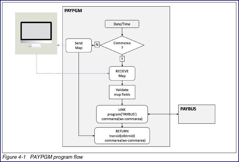
PAYPGM is the presentation logic program that collects information from the screen which includes the users desired function and passes it to the business logic
program for processing using a CICS LINK command.
4.1.1 Commarea
The presentation logic program and business logic program communicate via a commarea (Communication area) which we will explore first (Figure 4-2).
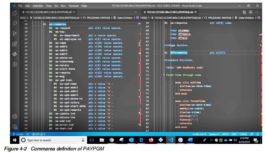
The commarea appears in the Working Storage Section of PAYPGM with its field names specified, and in Linkage section of PAYPGM as a place holder for future
invocations.
In PAYBUS the fields appear and are used through the Linkage Section.
The reason for this is that PAYPGM will create the commarea out of working storage the first time through with the initial values.
On subsequent requests PAYPGM will move the data from Linkage to Working Storage to process any of the field data.
This is a standard that can be seen in many CICS programs.
Looking at the actual fields in the commarea, the first ten bytes need to be collected and passed to the business logic program, PAYBUS.
More specifically, the four byte request, followed by a one byte department number and a five byte employee number.
This makes up the data that needs to be collected from the user.
The remainder of the commarea is either data from the record being retrieved and displayed on the screen or a set of one byte indicators to provide the state
information.
They are represented as flags and can either be an ‘n’ or a ‘y’.
Initially they are all set to ‘n’ and as we progress through the program logic we will see when they change.
4.1.2 First time through processing
Next let’s have a look at first time through processing (Figure 4-3).
This processing will be different depending on the programmer’s preference or if commareas are not used, as example if you use channels and containers, but
otherwise it is the most popular method of determining first entry into a program.

The first bit of code is to get the time and date using CICS commands.
These are displayed on the screen every time the user presses a key, so they appear at the top of the procedure division.
The EIB or Execute Interface Block is automatically inserted into CICS programs.
It has many useful fields on entry. One is EIBCALEN which contains the commarea length.
If the commarea length is zero there is no commarea, so hence this is the first time through when using commarea.
Otherwise, If the user ends this task with a commarea, which we will see, then on subsequent calls it will never be zero.
The first time through this program the BMS map is prepped with the time, date and a message to the user to enter data, then the MAP is sent.
It is the return command with tranid and commarea option that is the most interesting.
You can see that the return is nominating the next transaction to run using EIBTRNID which is the current transaction id.
This means should the user pressed enter or a function key the very same transaction PAYR will run.
You can also see that how the commarea to be passed to the next invocation of this program is coded.
4.1.3 Function evaluation
Now we will explore some standard programming found in a presentation logic program.
We will start with an evaluation of the function requested and move on to receiving the data from the screen (Figure 4-4).

As you can see from the evaluate statement the key that the user pressed is passed to a CICS program in an EIB field called EIBAID.
The program is structured to evaluate the key and set the request based on the key pressed.
Once done a routine called “DO-WORK” is performed and then you can see a familiar CICS return statement that nominates the successor transaction with the commarea
in place.
The DO-WORK paragraph starts by getting the data the user entered on the screen with a CICS RECEIVE MAP command.
In older versions of code an error called a MAPFAIL would be possible if the user did not enter any data as CICS maps were coded not to return fields that were
empty to avoid data transmission of blank fields.
Today the number of bytes of transmission is considered so small that if is more efficient to send all fields, entered or not, than run through the code required
to test if the field was entered.
4.1.4 Field validation and link to PAYBUS
The next section of code is all about field validation (Figure 4-5 and Figure 4-6).
Again this program has been structured for very simplistic field validation, most real life examples will have various complex routines to validate the data
entered by the user.


The long list of “IF” statements are simply checking to see if a field has been entered.
The program accomplishes this by checking the length returned from the RECEIVE command issued earlier.
If the length is greater than zero there is data to update in the commarea.
Notice how the program also updates the flag associated with each new field. From ‘n’ to ‘y’.
This will notify the business logic program that the data is new.
The last piece of this code is the call to the business logic (PAYBUS) to process the request.
It is a CICS LINK command where the data being passed is the commarea.
Rather than explore the business logic at this point, let us see what the presentation logic program does once the business logic returns to it.
Keep in mind that after the LINK is complete, we still need to check if that command executed properly.
4.1.5 Check return code from the link
Figure 4-7 starts by checking the return code from the LINK command of the prior screen to see if it executed successfully.
If not, you can see some common logic to return the error to the users screen.
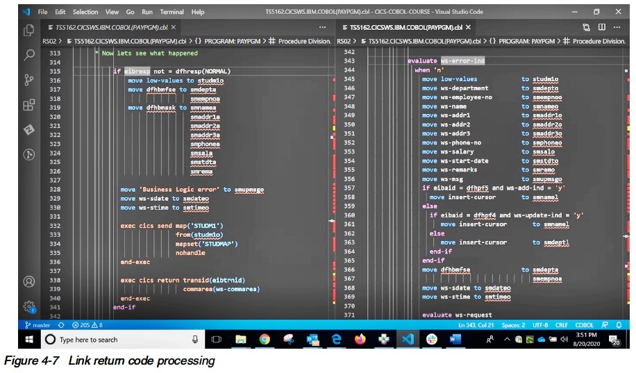
If the command itself worked, we still need to check if the business logic program returned an error by checking an error indicator flag.
If so, we return the business specific error message that was provided by the business logic program.
4.1.6 Remaining presentation logic processing
Assuming everything worked to this point we simply have some presentation house keeping to do prior to returning the results of the request back to the user
(Figure 4-8).
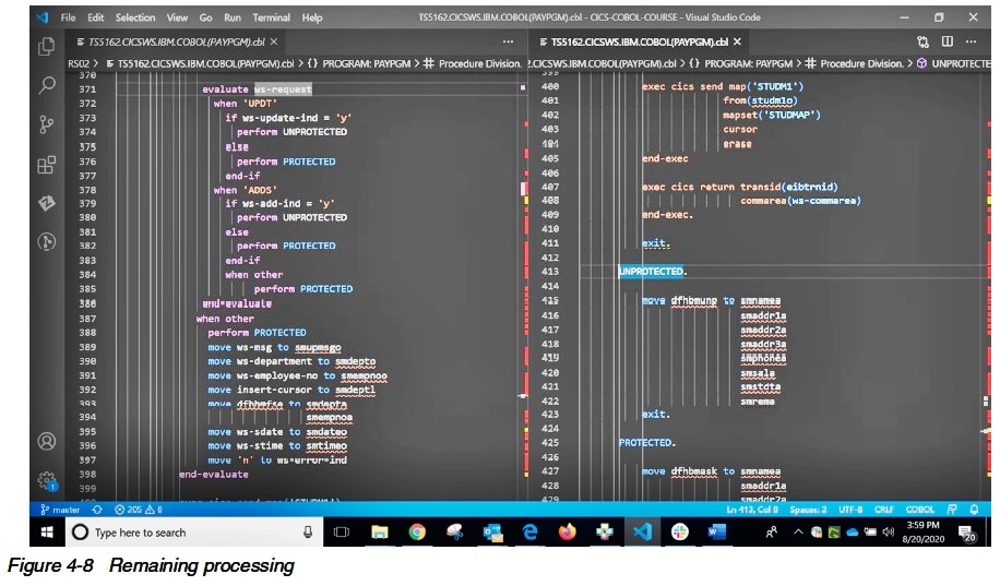
Most of the fields on the screen are protected until there is a need for the user to supply input.
In our application this is only required if the user updates an employee payroll record or adds a new employee.
In those specific cases, we need to modify the screen when responding to unprotect the fields.
The code here calls a routine to do protection and unprotection of input fields as required by the processing. It then sends the results to the user.
4.2 Business logic
The business logic program is the core piece of a CICS application.
It performs the functionality required by the application regardless of the user interface, and in most cases the datastore (Figure 4-9).
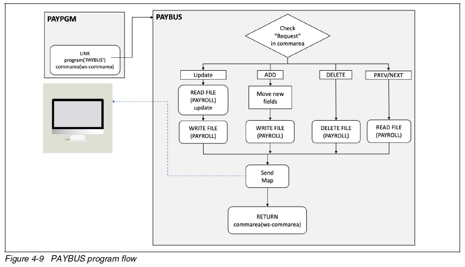
The business logic normally consists of a driver program that coordinates the execution of the business logic by invoking subsequent programs for different
functions.
In our case it is all in one. This program is not only the entire business logic but the datastore as well.
Let’s have a look at what it does.
4.2.1 commarea and special processing
PAYBUS receives data in its Linkage Section (Figure 4-10).
This is passed by its caller as a commarea. In this case, on an EXEC CICS LINK command.

The first section of code in this program is special processing for the 3270 presentation logic program.
The program begins by resetting flags should a user interrupt a function that is normally done in two steps using a 3270 screen.
They are the functions of ADD, UPDATE and DELETE.
If a user starts an update for example by pressing PF4 on the 3270 screen, but then does not confirm the update with a second PF4, the flags in the commarea need
to be reset to say we are no longer in middle of an update.
4.2.2 Request analysis
Once any special processing is complete, the business logic program will analyze the request and give control to the routine that process it (Figure 4-11).
Again, had this been a more complex application this might be calls to other programs to process these requests.
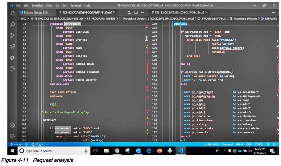
As we can see the first step is an evaluation of the request.
This is supplied in a commarea field passed. Based on the request type the function is performed.
The DISPLAY routine is the first routine highlighted here. It is normally the routine that simply reads a record and returns the contents to the caller.
However, the “IF” statement at the top implies it is also called from the FORWARD and BACKWARD routine without first reading a record.
Therefore, this DISPLAY routing is a generic routine for not only displaying the record, but also used by other routines to move data read from the VSAM file into
the commarea to return to the caller.
Lastly, note that an error from the read command assumes that the record was not found.
Of course, there are other errors to contend with such as “file not open” as an example.
We have simplified the code here for brevity; however, it is good practice to consider all possible errors, and send a proper response.
4.2.3 Updating a record
It is time to take a look at a more complex routine (Figure 4-12).

The first complication with this routine is that it is invoked twice.
The first time will verify that the record exists by calling the DISPLAY routine and present the record back to the caller.
This has two purposes. The first we just mentioned, the second is simply to unlock the fields on the 3270 display so the user can update only those fields they
want to update.
An example is raising a person’s salary.
The remainder of the record would remain unchanged but only that field would be updated.
CICS allows you to update a record by adding the attribute “UPDATE” to a regular READ command.
When the UPDATE is coded, CICS expects the REWRITE command to be issued next.
Note that a key does not have to be passed as CICS assumes that you are updating the record from a previous READ with the update attribute.
The remainder of the code between the READ UPDATE and REWRITE is about only updating the fields that the user has changed.
Leaving the remaining fields, the same as they were.
This is accomplished by using and testing flags sent by the caller.
There is also an additional piece of logic that collects a write a timestamp into the record.
Although not utilized in this piece of code, the idea is that if two people were trying to update the same record at the same time, one of the user's updates could
be lost.
In a production copy of this code there would be an extra test to make sure the timestamp of the record read and presented to the user matches the timestamp of the
record being updated.
If it changed the user would be warned that the record has changed since they last saw it and the update would fail.
The next question I would have as a programmer is what happens if the transaction abend or fails in middle of the update?
Would the new data or the old data be displayed on a lookup?
The answer is it depends.
The systems programmer controls whether a VSAM file is recoverable.
If it is any changes to a record are backed out if a failure occurs.
If this is not set, then the update will take place.
It is therefore important to have a discussion with your systems programmer about an application’s needs when dealing with issues such as recovery.
4.2.4 Adding a record
The next function is adding a record. It too is a twostep process like update (Figure 4-13).
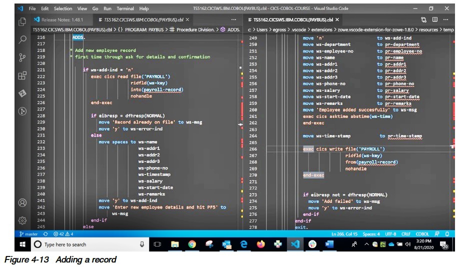
The first time through the ADD logic the program simply checks if the record exists.
If so, it sends back the record with a message that it is already on the file.
If the record does not exist, this program will clear all the fields that are required for adding a new record and return to the caller.
In the case of the 3270 presentation logic program this give it the chance to unlock the fields giving the user the ability to enter the new fields.
On the second request it adds the record presented by the user.
Note it also places a timestamp in the record as mentioned earlier for use with the UPDATE.
As with an UPDATE, should a failure occur during the run of this transaction, the record may or may not be added depending on the recoverability of the file.
4.2.5 Deleting a request
The next function to look at is a delete request (Figure 4-14).
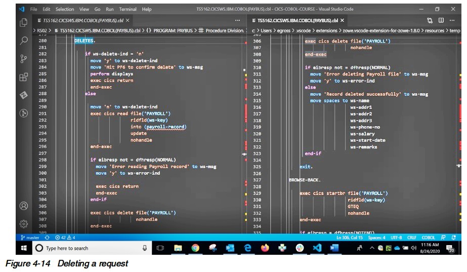
The DELETE request is quite interesting as it is also a twostep process, where a user presses PF6 to invoke a delete when entering a Department and Employee.
The first time through this program simply calls the DISPLAY routine to return the record back to the caller that they are about to delete.
Pressing PF6 a second time invokes the DELETE code.
Interestingly, the first thing this program will do as part of step two is a READ with the update flag on the record about to be deleted.
This is to ensure we lock the record verifying no other customer is in middle of an update.
Once the READ executes we have the record locked so we can subsequently delete it.
4.2.6 Browse forward and backwards
The last bit of code that we will look at in this program is the browse forward and backward (Figure 4-15).
As the code is practically identical between the two, they will be described together.
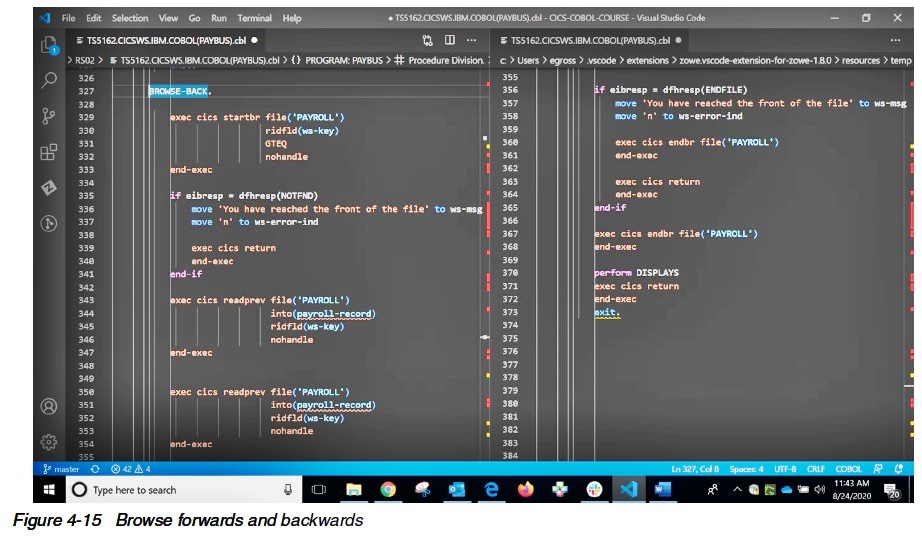
The concept of browsing through a keyed file is not new, but one that is used by many other products when accessing a keyed file.
In the case of CICS you can see that we start with a start browse command.
This command is presented with the key in which to start browsing from with the attribute GTEQ.
GTEQ means greater than or equal to.
This allows the positioning of the pointer to the record requested or the next one if this record does not exist.
So, if a customer wanted department one employee one and it does not exist, the system will automatically position the pointer to the next available record for
the browse forward and the previous record for the browse backward.
Should a not found condition be returned, it means we are at the front or back of the file, so we will notify the user that there are no more records prior or
after that key.
The next set of commands at first glance appear to be a bug.
Why would the programmer code two of the exact same commands one right after the other?
Well in this example they are readprev commands to browse backward.
However, you can check that if we were browsing forward, we still see two commands called readnext.
The answer in the case of readprev is that we are already pointing to the NEXT record to read.
The first readprev positions us at the current record, the next one backs up to the prior record.
Had we not done two of these we would end up reading the same record over and over again.
As you can imagine readnext works the same way.
The first readnext reads the current record as that is where we are positioned.
The next readnext will read the record following the current record.
Lastly, you can see that an ENDFILE condition means we are the start or end of the file depending on if we are going forward or backward so we return that error.
Also, as STARTBROWSE holds a pointer to the file, it is good coding etiquette to end the browse as soon as there are no more plans to browse the records.
Ending the task would work as well, however, if someone added code to this program and did not notice they were still in a browse it could cause problems in the
future.
Therefore, this program ends the browse as soon as it has no need to browse anymore records.
This document was created or updated on December 17, 2020.
© Copyright IBM Corp.
|

